Video of the Day

Showing posts with label Detector. Show all posts

Wednesday, March 2, 2016

0

Simple Motion Detector Using NE555 Timer Circuit

This circuit is based on a passive infrared (PIR) sensor, which automatically switches on a device when someone comes close to it. It can be used for detection of theft or an unauthorised person entering a restricted area or building. It can also turn on lights when someone approaches the area where it is installed. Applications of this circuit include security systems, corridor lights and bathroom lights, among others.
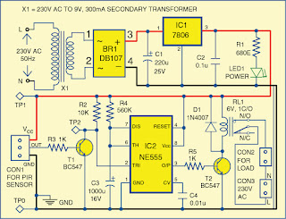
Simple Motion Detector Using NE555 Timer Circuit
Fig. 1: Circuit diagram of the motion detector

Circuit and working

The circuit diagram of the motion detector using NE555 timer is shown in Fig. 1. It is built around 230V AC primary to 9V, 300mA secondary transformer X1, bridge rectifier DB107 (BR1), 6V voltage regulator 7806 (IC1), timer NE555 (IC2) and a few other components.


The 230V AC mains is stepped down to 9V, 300mA through step-down transformer X1. Secondary output of X1 goes to bridge rectifier BR1. Capacitor C1 filters the ripples and the rectified output is given to regulator 7806 (IC1). IC1 provides 6V regulated DC output to operate the circuit. LED1 is used as a power-on indicator.

 IC2 is configured in monostable mode. Time period of IC2 is based on resistor R4 and capacitor C3, which is around ten minutes in this case. By changing resistor R4 and capacitor C3 you can change the time period of IC2.

Output pin 3 of IC2 is connected to the base of relay driver transistor T2. Contacts of relay RL1 are connected to the load, which could be a CFL or a bulb connected across CON2.

The PIR sensor is a pyroelectric device developed for detection of human body infrared radiations. It has a single output that goes high when a valid motion is detected. That is, the load is switched on whenever the PIR module senses a body in motion nearby.

Under normal conditions, transistor T1 is cut off and collector output is high around 6V. When motion is sensed, output pin (OUT) of the sensor becomes high, making transistor T1 to conduct for a few seconds, and voltage at its collector goes low momentarily. This low signal triggers IC2. Output pin 3 of IC2 goes high for around ten minutes, energising relay RL1 through transistor T2, turning on the load for ten minutes.

In brief, when someone comes in front of the PIR module, its output triggers IC2 to turn on the load. Thereafter it is disabled automatically.


Fig. 2: Actual-size PCB of the motion detector


Fig. 3: Component layout of the PCB

Construction and testing
An actual-size, single-side PCB for the motion detector using NE555 timer is shown in Fig. 2 and its component layout in Fig. 3. Enclose the PCB in a box and install it at a suitable location. Connect the PIR module across CON1.

Connect transformer X1 to 230V AC mains. Verify various test point voltages as given in the table to ensure proper working before using the circuit.


Sourced By: EFY Author :  Kumar Abhisekh


Sunday, January 10, 2016

0

Simple Motion Detector Using NE555 Timer

This circuit is based on a passive infrared (PIR) sensor, which automatically switches on a device when someone comes close to it. It can be used for detection of theft or an unauthorised person entering a restricted area or building. It can also turn on lights when someone approaches the area where it is installed. Applications of this circuit include security systems, corridor lights and bathroom lights, among others.

Simple Motion Detector Using NE555 Timer
 Fig. 1: Circuit diagram of the motion detector

Circuit and working

The circuit diagram of the motion detector using NE555 timer is shown in Fig. 1. It is built around 230V AC primary to 9V, 300mA secondary transformer X1, bridge rectifier DB107 (BR1), 6V voltage regulator 7806 (IC1), timer NE555 (IC2) and a few other components.

The 230V AC mains is stepped down to 9V, 300mA through step-down transformer X1. Secondary output of X1 goes to bridge rectifier BR1. Capacitor C1 filters the ripples and the rectified output is given to regulator 7806 (IC1). IC1 provides 6V regulated DC output to operate the circuit. LED1 is used as a power-on indicator.


IC2 is configured in monostable mode. Time period of IC2 is based on resistor R4 and capacitor C3, which is around ten minutes in this case. By changing resistor R4 and capacitor C3 you can change the time period of IC2.

Output pin 3 of IC2 is connected to the base of relay driver transistor T2. Contacts of relay RL1 are connected to the load, which could be a CFL or a bulb connected across CON2.

The PIR sensor is a pyroelectric device developed for detection of human body infrared radiations. It has a single output that goes high when a valid motion is detected. That is, the load is switched on whenever the PIR module senses a body in motion nearby.

Under normal conditions, transistor T1 is cut off and collector output is high around 6V. When motion is sensed, output pin (OUT) of the sensor becomes high, making transistor T1 to conduct for a few seconds, and voltage at its collector goes low momentarily. This low signal triggers IC2. Output pin 3 of IC2 goes high for around ten minutes, energising relay RL1 through transistor T2, turning on the load for ten minutes.

In brief, when someone comes in front of the PIR module, its output triggers IC2 to turn on the load. Thereafter it is disabled automatically.


Fig. 2: Actual-size PCB of the motion detector


Fig. 3: Component layout of the PCB

Construction and testing
An actual-size, single-side PCB for the motion detector using NE555 timer is shown in Fig. 2 and its component layout in Fig. 3. Enclose the PCB in a box and install it at a suitable location. Connect the PIR module across CON1.

Connect transformer X1 to 230V AC mains. Verify various test point voltages as given in the table to ensure proper working before using the circuit.


Sourced By: Efy  Author: Kumar Abhisekh


Friday, November 14, 2014

0

New Simple Lie detector Circuit Diagram

This is the New Simple Lie detector Circuit Diagram. The two probes shown are held in the hands and the skin resistance applies bias to the transistor. 

 New Simple Lie detector Circuit Diagram


New Simple Lie detector Circuit Diagram


The 5 k ohm pot is set for zero deflection on the meter. When the ' 'subject'' is embarrassed or lies, sweating on the hands takes place, increasing the bias to the transistor and upsetting the bridge balance.


Sunday, November 2, 2014

0

Simple Resistance ratio Detector Circuit Diagram

This is the Simple Resistance ratio Detector Circuit Diagram.  Photoelectric control, temperature detection and moisture sensing require a circuit that can accurately detect a given resistance ratio. A simple technique that uses an op amp as a sensing element can provide 0,5% accuracy with low parts cost. The reed-relay contacts close when the resistance of the sensor Rp equals 47% of the standard Rs. 

 Simple Resistance ratio Detector Circuit Diagram

Simple Resistance ratio Detector Circuit Diagram


Adjusting either Rl or R2 provides a variable threshold; the threshold is controlled by varying R3. For the most part, the type of resistors used for Rl and R2 determines the accuracy and stability of the circuit. With metal-film resistors, less than 0.5% change in ratio sensing occurs over the commercial temperature range (0 to 70 C) with ac input variations from 105 to 135 V.


Wednesday, February 26, 2014

0

Simple Electromagnetic Field Detector Schematic

This circuit is sensitive to low frequency electromagnetic radiation and will detect for example hidden wiring or the field that encompasses a transformer. Pickup is by a radial type inductor, used as a probe which responds well to low frequency changing magnetic and electric fields. Ordinary headphones are used to for detection. The field that surrounds a transformer is heard as a 50 or 60Hz buzz. The circuit is below:-

Electromagnetic Field Detector Circuit Diagram
Detector-Circuit-Diagram
Notes:
I threaded a length of screened cable through an old pen tube and soldered the ends to a radial type can inductor. I used 1mH. The inductor fitted snugly into the pen tube. The opposite end of the cable connects to the input of the op-amp. Any op-amp should work here, possibly better results may be achieved with a low noise FET type such as the LF351. The 2M2 potentiometer acts as a gain control and the output is a pair of headphones. Stereo types can be used if they are wired as mono. I used an 8 ohm type, but the circuit should work equally well with higher impedance types. The probe (shown below) may be connected via screened cable and a 3.5mm stereo plug and socket.


Field-Detector-Circuit-Diagram
Detection:
The sensitivity of this circuit is good. Mains wiring buried an inch in plaster can be detected with precision. A small load on the electric supply is all that is needed; a 20 watt desk lamp or similar will suffice. The hum field surrounding a transformer can be detected oat over 7 inches. Domestic appliances such as videos and alarm clocks all produce interference which can be heard with the probe. The electric field surrounding a loudspeaker or earpiece can also be heard. Try lifting a telephone and place the probe near the earpiece. A telephone pickup coil can be used in place of the inductor if desired. I will make an improved version of this circuit with a meter output later.


Tuesday, January 14, 2014

0

Invisible Broken Wire Detector

Portable loads such as video cameras, halogen flood lights, electrical irons, hand drillers, grinders, and cutters are powered by connecting long 2- or 3-core cables to the mains plug. Due to prolonged usage, the power cord wires are subjected to mechanical strain and stress, which can lead to internal snapping of wires at any point. In such a case most people go for replacing the core/cable, as finding the exact location of a broken wire is difficult.

In 3-core cables, it appears almost impossible to detect a broken wire and the point of break without physically disturbing all the three wires that are concealed in a PVC jacket. The circuit presented here can easily and quickly detect a broken/faulty wire and its breakage point in 1-core, 2-core, and 3-core cables without physically disturbing wires. It is built using hex inverter CMOS CD4069.

Gates N3 and N4 are used as a pulse generator that oscillates at around 1000 Hz in audio range. The frequency is determined by timing components comprising resistors R3 and R4, and capacitor C1. Gates N1 and N2 are used to sense the presence of 230V AC field around the live wire and buffer weak AC voltage picked from the test probe. The voltage at output pin 10 of gate N2 can enable or inhibit the oscillator circuit.

When the test probe is away from any high-voltage AC field, output pin 10 of gate N2 remains low. As a result, diode D3 conducts and inhibits the oscillator circuit from oscillating. Simultaneously, the output of gate N3 at pin 6 goes ‘low’ to cut off transistor T1. As a result, LED1 goes off. When the test probe is moved closer to 230V AC, 50Hz mains live wire, during every positive half-cycle, output pin 10 of gate N2 goes high.

Thus during every positive half-cycle of the mains frequency, the oscillator circuit is allowed to oscillate at around 1 kHz, making red LED (LED1) to blink. (Due to the persistence of vision, the LED appears to be glowing continuously.) This type of blinking reduces consumption of the current from button cells used for power supply. A 3V DC supply is sufficient for powering the whole circuit.


Invisible Broken Wire Detector
 Invisible Broken Wire Detector Circuit Diagram

AG13 or LR44 type button cells, which are also used inside laser pointers or in LED-based continuity testers, can be used for the circuit. The circuit consumes 3 mA during the sensing of AC mains voltage. For audio-visual indication, one may use a small buzzer (usually built inside quartz alarm time pieces) in parallel with one small (3mm) LCD in place of LED1 and resistor R5. In such a case, the current consumption of the circuit will be around 7 mA.

Alternatively, one may use two 1.5V R6- or AA-type batteries. Using this gadget, one can also quickly detect fused small filament bulbs in serial loops powered by 230V AC mains.
The whole circuit can be accommodated in a small PVC pipe and used as a handy broken-wire detector. Before detecting broken faulty wires, take out any connected load and find out the faulty wire first by continuity method using any multimeter or continuity tester.

Then connect 230V AC mains live wire at one end of the faulty wire, leaving the other end free. Connect neutral terminal of the mains AC to the remaining wires at one end. However, if any of the remaining wires is also found to be faulty, then both ends of these wires are connected to neutral. For single-wire testing, connecting neutral only to the live wire at one end is sufficient to detect the breakage point.

In this circuit, a 5cm (2-inch) long, thick, single-strand wire is used as the test probe. To detect the breakage point, turn on switch S1 and slowly move the test probe closer to the faulty wire, beginning with the input point of the live wire and proceeding towards its other end. LED1 starts glowing during the presence of AC voltage in faulty wire. When the breakage point is reached, LED1 immediately extinguishes due to the non-availability of mains AC voltage.

The point where LED1 is turned off is the exact broken-wire point. While testing a broken 3-core rounded cable wire, bend the probe’s edge in the form of ‘J’ to increase its sensitivity and move the bent edge of the test probe closer over the cable. During testing avoid any strong electric field close to the circuit to avoid false detection.
Author: K. Udhaya Kumaran


Social Time

Google Plus
Follow Us
Pinterest
Follow Us

Subscribe to our newsletter

(Get fresh updates in your inbox. Unsubscribe at anytime)