Video of the Day

Showing posts with label All Switches. Show all posts

Friday, August 4, 2017

0

Simple Switch Mode Power Supply

The SMPS described here is suit-able for high-wattage stereos and other similar equipment. The circuit employs two high-voltage power transistors (BU208D) which have built-in re-verse-connected di-odes across their collectors and emitters. It can supply about 250-watt out-put. The circuit uses a ferrite core transformer of 14mm width, 20mm height, and 42mm length of E-E cores. An air gap of 0.5 mm is required between E-E junction. Good insulation using plastic-insulating sheets (Mylar) is to be maintained between each layer of winding. 

 
Simple Switch Mode Power Supply Circuit Diagram

Simple Switch Mode Power Supply Circuit Diagram
 
The number of primary turns required is 90 with 26 SWG wire. The secondary winding employs 17 SWG wire (for 4A load current). Each turn of the secondary develops approximately 2 volts. The reader can decide about the output volt-age and the corresponding secondary turns, which would work out to be half the desired secondary voltage. The volt-age rating of capacitors C7 and C8 should be at least twice the secondary output of each secondary section. BY396 rectifier diodes shown on the secondary side can be used for a maximum load current of 3 amperes. 

Two feedback windings (L1 and L2) using two turns each of 19 SWG wire are wound on the same core. These windings are connected to transistors T1 and T2 with a phase difference of 180o,  as shown by the polarity dots in the figure. First wind the primary winding (90 turns using 26 SWG wire) on the former. Then wind the two feedback windings over the secondary (output). Ensure that each winding is separated by an insulation layer.  Two separate heat sinks are to be pro-vided for the two transistors (BU208D). 

The filter capacitor for mains should be of at least 47µF, 350V rating. It is better to use a 100µF, 350V capacitor. If the output is short-circuited by less than 8-ohm load, the SMPS would automatically turn off because of the absence of base current.  The hfe min (current amplification factor) of BU208D is 2.5. Thus, sufficien base current is required for fully satu rated operation, otherwise the transistors get over-heated. At times, due to use of very high value of capacitors C7 and C8 (say 2200mF or so) on the secondary side or due to low load, the oscillations may cease on the primary side. This can be rectified by increasing the value of capacitor C6 to 0.01mF. 


Saturday, July 1, 2017

0

Green USB switch


Green USB switch Circuit Diagram. According to the Energy Saving  Trust, if you add up all the current drawn in standby mode by items such as stereos, TVs, VCRs and DVDs over a year in the UK alone, it amounts to 3.1 million tonnes of CO2 released into the atmosphere.This is without factoring in the current drawn by all the PCs,laptops and their associated peripherals left in standby mode. 

Circuit diagram :


Green USB switch Circuit Diagram

It  is  not  necessary  to  spend  a  great deal of money or time to  make a difference on a personal  level. The circuit described here  is designed for use by laptop or  notebook computers. It will automatically switch off all mains  powered peripheral equipment  including monitor, printer, scanner, TV tuner and USB hub etc  when it detects that the notebook  is switched off. The circuit is quite  straightforward; in addition to an  optocoupler it requires a 12 V  double-pole  relay  with  mains  rated contacts and a small power  supply  for  the  optocoupler.  When the laptop is switched on  5 V appears at the USB socket,  activating the relay and switching  through  the  mains  supply  on K3 and K4. The notebook’s  USB socket is still available to be  used as normal but it’s worth remembering that the optocoupler  takes a few milliamps from the  USB supply and this may cause a  problem if a high-current device  is plugged into the USB socket.  In the case where the laptop has  more than enough USB sockets it may be worthwhile us-ing one of them solely for this  circuit, the extension USB connector K2 would then not be  required. 

The circuit is mounted into a  mains plug enclosure which  provides a socket where the  mains extension strip will be  plugged into. With any luck  there will be sufficient space  to fit the entire circuit into the  mains extension strip enclosure and save the need for a  separate enclosure. The slow-blow 6.3-A fuse (F1) protects  the equipment plugged into  the strip. 

In  addition  to  the  optocoupler  and relay the circuit also has a  ‘freewheel’ diode D1 and a relay  driver formed by T1 and its base  bias voltage divider network R2/ R4. The two ‘snubber’ networks  C1/R3 and C2/R5 reduce the  possibility of arcing which can  occur  when  the  relay  contacts  open (especially with inductive  loads). Capacitors C1 and C2  must be class X2 types which  can handle mains voltage plus any  spikes.  The  power  supply  consists of a small mains trans-former  (12 V,  50 mA),  bridge  rectifier and smoothing capacitor C3. 

The laptop’s mains adaptor itself  can also be switched by this circuit when the laptop is fitted with  its rechargeable battery which  allows the computer to boot up  without a mains supply. The en-tire USB switch circuit draws cur-rent even when it is off but this value  is  tiny  compared  to  the  combined standby current of all  the peripherals. 

Note that parts of this circuit are  connected to the (potentially lethal) mains supply voltage; it is  essential to provide protection  to ensure that nothing can accidentally make contact with these  parts of the circuit. It is also important to observe correct separation between parts of the circuit carrying low voltage and  those carrying the high volt-age. Please observe the electrical Electrical Safety guide-lines which are reprinted in  Elektor  Electronics  several  times a year. 

The  circuit  is  less  suitable  for use with desktop PCs be-cause  the  majority  of  these  machines supply 5 V over the  USB socket even though they  have been shut down via soft-ware. The only way to turn off  in this case is to reach around  the back of the machine and  switch off at the main switch. 


Author : Wolfram Winfera - Copyright : Elektor


Saturday, June 24, 2017

0

Simple Electronic Lock

Simple Electronic Lock Circuit diagram. There are six (or more) push switches. To 'unlock' you must press all the correct ones at the same time, but not press any of the cancel switches. Pressing just one cancel switch will prevent the circuit unlocking. When the circuit unlocks it actually just turns on an LED for about one second, but it is intended to be adapted to turn on a relay which could be used to switch on another circuit. Please Note: This circuit just turns on an LED for about one second when the correct switches are pressed. It does not actually lock or unlock anything!

Simple Electronic Lock Circuit diagram :

Simple Electronic Lock Circuit Diagram

Stripboard Layout :


Parts :
  • resistors: 470, 100k ×2, 1M
  • capacitors: 0.1μF, 1μF 16V radial
  • on/off switch
  • push-switch ×6 (or more)
  • stripboard 12 rows × 25 holes
  • red LED
  • 555 timer IC
  • 8-pin DIL socket for IC
  • battery clip for 9V PP3
  •  
A kit for this project is available from RSH Electronics: www.kpsec.freeuk.com

Copyright :John Hewes 2006,  The Electronics Club


Wednesday, October 29, 2014

0

Simple Overtone oscillator with crystal switching Circuit Diagram

This is the Simple Overtone oscillator with crystal switching Circuit Diagram. The large inductive phase shift of LI is compensated for by Cl Overtone crystals have very narrow bandwidth;, the re fore, the trimmer has a smaller effect than for fundamental-mode operation. 

Simple Overtone oscillator with crystal switching Circuit Diagram


Simple Overtone oscillator with crystal switching Circuit Diagram


Saturday, March 1, 2014

0

Simple Energy-Saving Switch Schematic Diagram

Lights do not always need to be on at full power. Often it would be useful to be able to turn off the more powerful lights to achieve softer illumination, but this requires an installation with two separately-switch-able circuits, which is not always available.
. .
 Energy-Saving Switch Circuit Image
Switch-Circuit-Image

If the effort of chasing out channels and replastering for a complete new circuit is too much, then this circuit might help. Normal operation of the light switch gives gentle illumination (LA1). For more light, simply turn the switch off and then immediately (within 1 s) on again. The circuit returns to the gentle light set-ting when switched off for more than 3 s. There is no need to replace the light switch with a dual version: simply insert this circuit between switch and lamp.
.
Energy-Saving Switch Circuit Diagram

Energy-saving Switch-Circuit-Diagram
Parts List:
Resistors:
R1 = 100Ω
R2 = 680Ω
Capacitor:
C1 = 4700µF 25 V
Semiconductors:
D1,D2 = 1N4001
Miscellaneous:
K1,K2,K3 = 2-way PCB terminal
block, lead pitch 7.5 mm
F1 = fuse, 4AT (time lag) with PCB
mount holder
TR1 = mains transformer, 12V @ 1.5
VA, short-circuit proof, PCB mount
B1 = B80C1400, round case (80V
piv, 1.4A)
RE1 = power relay, 12V, 2 x c/o,
PCB mount
RE2 = miniature relay, 12V, 2 x c/o,
PCB moun

How does it work?
Almost immediately after switch-on, fast-acting miniature relay RE2 pulls in, since it is connected directly after the bridge rectifier. Its nor-mallyclosed contact then isolates RE1 from the supply, and thus current flows to LA1 via RE1’s normally-closed con-tact. RE1 does not have time to pull in as it is a power relay and thus relatively slow. Its response is also slowed down by the time constant of R1 and C1. If the current through the light switch is briefly interrupted, RE2 drops out immediately. There is enough energy stored in C1 to activate RE1, which then holds itself pulled in via a second, normally-open, contact. If current starts to flow again through the light switch within 1s, LA2 will light. To switch LA1 back on it is necessary to turn the light switch off for more than 3 s, so that C1 can discharge via R2 and RE1. The printed circuit board can be built into a well insulating plastic enclosure or be incorporated into a light fitting if there is sufficient space.
.
PCB-Layout
Circuit-Diagram
Caution:
the printed circuit board is connected directly to the mains-powered lighting circuit. Every precaution must be taken to prevent touching any component or tracks, which carry dangerous voltages. The circuit must be built into a well insulated ABS plastic enclosure.


Thursday, February 20, 2014

0

Simple Automatic Load Sensing Power Switch

This circuit will automatically switch on several mains-powered "slave" loads when a "master" load is turned on. For example, it will switch on the amplifier and CD player in a stereo system when the receiver is turned on. It works by sensing the current draw of the "master" device through a low value high wattage resistor using a comparator. The output of that comparator then switches on the "slave" relay. The circuit can be built into a power bar, extension cord or power center to provide a convenient set of "smart" outlets that switch on when the master appliance is powered (turn on the computer monitor and the computer, printer and other peripherals come on as well).
.
 Simple Automatic Load Sensing Power Switch Circuit Diagram


Simple Automatic Load Sensing Power Switch

Parts


Part            


  Total Qty.


Description


C1, C3               2               10uF 35V Electrolytic Capacitor
C2     1               1uF 35V Electrolytic Capacitor
R1     1               0.1 Ohm 10W Resistor
R2     1               27K 1/2W Resistor
R3, R4     1               1K 1/4W Resistor
R5     1               470K 1/4W Resistor
R6     1               4.7K 1/2W Resistor
R7     1               10K 1/4W Resistor
D1, D2, D4     3               1N4004 Rectifier Diode
D3     1               1N4744 15V 1 Watt Zener Diode
U1     1               LM358N Dual Op Amp IC
Q1     1               2N3904 NPN Transistor
K1     1               Relay, 12VDC Coil, 120VAC 10A Contacts
S1     1               SPST Switch 120AVC, 10A
MISC     1               Board, Wire, Socket For U1, Case, Mains Plug, Socket
 .
Notes
  • This circuit is designed for 120V operation. For 240V operation, resistors R2 and R6 will need to be changed.
  • A maximum of 5A can be used as the master unless the wattage of R1 is increased         S1 provides a manual bypass switch.
  • THis circuit is not isolated from the mains supply. Because of this, you must exercise extreme caution when working around the circuit if it is plugged in.


Tuesday, February 18, 2014

0

CELL-PHONE-CONTROLLED AUDIO/ VIDEO MUTE SWITCH

This cell-phone-controlled audio/video mute switch is highly useful in automobiles. The circuit automatically disconnects power supply to the audio/video system whenever the mobile handset is lifted off the holder for making or receiving a call. You can use any readily available cell-phone holder with some minor alterations or fabricate it yourself as shown in Fig. 1.

http://streampowers.blogspot.com/2014/02/cell-phone-controlled-audio-video-mute.html


Fig. 1: Proposed cell-phone holder

The circuit is wired around IC LM555 (IC1), the CMOS version of timer NE555, as shown in Fig. 2. IC1 is used as a medium-current line driver with either an inverting or non-inverting output. It can sink (or source) current of up to 50 mA only, so take care while handling it. The audio/video system is connected to the circuit via normally opened (N/O) contacts of the relay.

The circuit of the cell phone-controlled audio/video mute switch

Fig. 2: The circuit of the cell phone-controlled audio/video mute switch

When the cell phone is in its holder, LDR1 does not receive any light from white LED1 and its resistance is high. As a result, the voltage at pin 2 of IC1 remains high to provide a low output at pin 3. The low output of IC1 activates relay RL1 and the audio/video system gets power supply via its N/O contacts. LED3 glows to indicate that the audio/video system is ‘on.’When the handset is taken off the holder, light rays from LED1 fall on LDR1 and its resistance decreases. As a result, the voltage at pin 2 of IC1 decreases to provide a high output at its pin 3. The high output of IC1 deactivates relay RL1 and the audio/video system does not get power supply. LED2 glows to indicate that the audio/video system is ‘off.’

Preset VR1 is used to control the sensitivity of the circuit. Zener diode ZD1 is used for protecting white LED1 from the higher voltage. The circuit works off a 12V car battery. Switch S1 can be used to manually switch on/off the audio/video system.


Sourced By: EFY Author name:  T.K. HAREENDRAN


Friday, February 14, 2014

0

8-Digit Code Lock for Appliance Switching Circuit Diagram

This code lock is useful for appliances requiring exclusive or authorised use by those who know the preset code. If desired, the code can be changed.

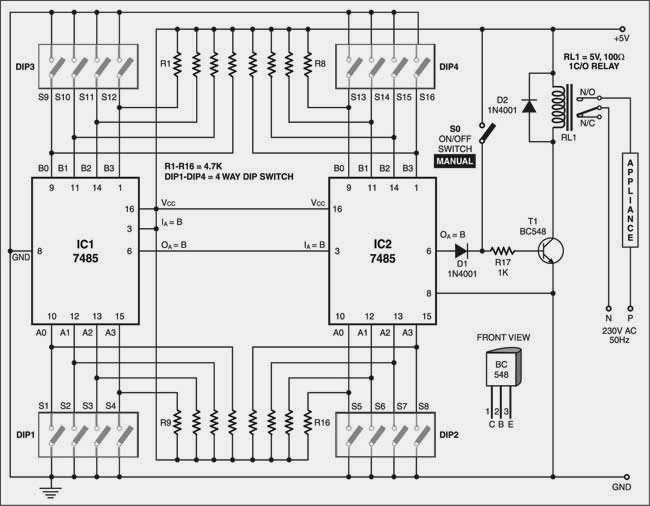
The circuit doesn’t require additional AND or NOT gate operations at the outputs. It uses two pairs of 4-way DIP switches. The code is set using DIP switches DIP3 and DIP4. Then these two switches are hidden inside the assembly. With DIP3 and DIP4, up to 256 code combinations are possible. The unlocking code is set by the user using DIP switches DIP1 and DIP2, which is compared with the preset code entered earlier via DIP3 and DIP4. If the two codes match, transistor T1 conducts.


8-Digit Code Lock for Appliance Switching Circuit Diagram
 

The codes are compared using two cascaded 4-bit magnitude comparator Ics (IC1 and IC2). If the input nibble present at DIP1 matches with preset DIP3 nibble, output pin 6 of IC1 (connected to input pin 3 of IC2) goes high. Now if nibble present at DIP2 matches with the preset nibble at DIP4, pin 6 of IC2 also goes high. This high output drives transistor T1 and the appliance turns on via relay contacts.

After use, disturb the positions of DIP1 and DIP2 so that the appliance can’t be operated by unauthorised persons. This will also switch the appliance off.

The circuit works off a 5V DC power supply. Hidden switch S0 can be used  to manually turn on/off the appliance if you have forgotten the preset code.

Caution. You may use this code lock at your own risk. After all, a clever intruder will try all 256 possible combinations one after the other to break the secret code.


Author :  Maneesh Chadha Sorced By : EFY


Saturday, February 1, 2014

0

12V Touch Switch Exciter

This circuit is designed to generate a 20KHz pseudo sine wave signal that can power about 50 remote touch activated switch circuits.  It can support a cable length of about 2500 feet.  A typical remote switch circuit is also shown as well as a receiver circuit for those switches.

12V Touch Switch Exciter Circuit Diagram


http://streampowers.blogspot.com/2012/08/12v-touch-switch-exciter.html
Source: DiscoverCircuits


Wednesday, January 29, 2014

0

Electronic Street Light Switch Circuit Digram

Here’s a simple and low-cost street light switch. This switch automatically turns on the light at sunset and turns it off at sunrise. The automatic function saves electricity besides man-power.

Broadly, the circuit can be divided into power supply and switching sections.

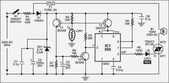
Pressing switch S1 connects mains to power the circuit. Mains is stepped down to 9.1V DC by resistor R1, diode D1 and zener diode ZD1. The output across ZD1 is filtered by capacitors C1 and C2. The output voltage can be increased up to 18V or decreased to 5V by changing the value of zener diode ZD1.

The switching circuit is built around light-dependent resistor LDR1, transistors T1 through T3 and timer IC1. The resistance of LDR1 remains low in daytime and high at night. Timer IC1 is designed to work as an inverter, so a low input at its pin 2 provides a high output at pin 3, and vice versa. The inverter is used to activate triac 1 and turn street bulb B1 on.

Electronic Street Light Switch Circuit Digram

Electronic Street Light Switch Circuit Digram


During daytime, light falls on LDR1 and transistors T1 and T2 remain cut-off to make pins 4 and 8 of IC1 low. Since transistor T3 is also cut-off, IC1 is not triggered. As a result, output pin 3 of IC1 (connected to the gate of triac 1 via resistor R5 and red LED1) remains low and the street bulb does not glow.

At night, no light falls on LDR1 and transistors T1 and T2 conduct to make pins 4 and 8 of IC1 high. Due to the conduction of transistor T3, trigger pin 2 of IC1 remains low. The high output of IC2 at its pin 3 turns the street bulb ‘on.’

Assemble the circuit, except LDR1, on any general-purpose PCB. Use long wires for LDR1 connections so that it can be mounted at a place where sufficient light falls on it.

Author :  Prince Philips


Sunday, January 26, 2014

0

Sound Activated Switch II

With this sound activated switch, control by sound may be very useful, not just on a robot but also for a bit of home automation, for example a sound-activated light responding to a knock on the door or a hand clap. The light will be automatically switched off after a few seconds. An alternative use is burglar protection — if someone wants to open the door or break something the light will come on, suggesting that someone’s at home. The circuit can work from any 5–12 VDC regulated power supply provided a relay with the suitable coil voltage is used.

Sound activated switch circuit diagram
Circuit Project: Sound Activated Switch circuit

When you first connect the supply voltage to the sound activated switch circuit, the relay will be energised because of the effect of capacitor C2. Allow a few seconds for the relay to be switched off. You can increase or decrease the ‘on’ period by changing the value of C2. A higher value results in a longer ‘on’ period, and vice versa. Do not use a value greater than 47μF.

Biasing resistor R1 determines to a large extent the microphone sensitivity. An electret microphone usually has one internal FET inside which requires a bias voltage to operate. The optimum bias level for response to sound has to be found by trial and error. All relevant electrical safety precautions should be observed when connecting mains powered loads to the relay contacts.


Social Time

Google Plus
Follow Us
Pinterest
Follow Us

Subscribe to our newsletter

(Get fresh updates in your inbox. Unsubscribe at anytime)