Video of the Day

Thursday, November 27, 2014

0

TDA 2050 - LM 1875 Power Amplifier Cirrcuit Diagram

This is the IC based TDA 2050 - LM 1875 Audio Power Amplifier Cirrcuit Diagram. This is not an usual circuit, but an attempt to make a PCB that is suitable for TDA2050 and LM1875 and has all the necessary circuitry on board - power supply, speaker protection, delayed turn-on and fast turn-off. This is achieved using the convenient uPC1237 IC.

TDA2050 and LM1875 are pin to pin compatible, the differences in their schematics are the values of a couple resistors and one capacitor. All this allows to make an universal circuit board, suitable for any of these two ICs.It is 2x30W, but it depend of the power supply voltage and the impedance of the speakers connected to the output.

TDA 2050 - LM 1875 Power Amplifier Cirrcuit Diagram


TDA 2050 - LM 1875 Power Amplifier Cirrcuit Diagram


PCB top layer

PCB top layer


PCB bottom layer

PCB bottom layer


Parts List

B1 KBU8M FBU4
C1 100nF C050-024X044
C2 100nF C050-024X044
C3 1000uF E5-10,5
C4 1000uF E5-10,5
C6 2.2uF C050-075X075
C7 220nF C050-030X075
C8 22uF E3,5-8
C9 100nF C050-024X044
C10 100nF C050-024X044
C11 1000uF E5-10,5
C12 1000uF E5-10,5
C13 4.7uF E2,5-6
C14 2.2uF C050-075X075
C15 220nF C050-030X075
C16 22uF E3,5-8
C17 4700uF E7,5-18
C18 4700uF E7,5-18
C19 47uF E2,5-7
C20 22uF E3,5-8
C21 22nF C050-025X075
D5 1N4148 DO35-7
D6 1N4004 DO41-10
D7 BZX85C12V DO41Z10
H1 MOUNT-PAD-ROUND3.0 3,0-PAD
IC1 LM1875 T05D
IC2 LM1875 T05D
IC3 UPC1237 SOP8
IN 6410-02
IN1 6410-02
J1 OUT1 AC2
J2 OUT2 AC2
J3 AC AC3
JP1 JP1
K1 G2R2 G2R2
LED 6410-02
LED2 LED5MM
LED3 6410-02
R1 1k 0207/2V
R2 20k 0207/12
R3 22k 0207/7
R4 1M 0207/7
R5 1R 0414V
R6 1k 0207/2V
R7 20k 0207/12
R8 22k 0207/7
R9 1M 0207/7
R10 1R 0414V
R11 2k2 0207/7
R12 120k 0207/7
R13 120k 0207/10
R14 56k 0207/7
R15 9k1 0207/7
R16 10k 0207/7
R17 92k 0207/10
R18 330R 0207/10
R19 68k 0207/7
R20 3k9 0207/10
R21 10k 0207/7
T2 MPSA42 TO92-EBC


Author: Hristo - xristostyahoo.com Sourced By: Circuitsproject


Tuesday, November 25, 2014

0

Simple Simulated inductor Circuit Diagram

This is the Simple Simulated inductor Circuit Diagram. In the this circuit With a constant current excitation, the voltage dropped across an inductance in-(in creases with frequency. Thus, an active device whose output increases with frequency can be characterized as an inductance. 

 Simple Simulated inductor Circuit Diagram

 Simple Simulated inductor Circuit Diagram


The circuit yields such a response with the effective inductance being equal to: L = R1R2C. The Q of this inductance depends upon Rl being equal to R2. At the same time, however, the positive and negative feedback paths of the amplifier are equal leading to the distinct possibility of instability at high frequencies. Rl should, therefore, always be slightly smaller than R2 to assure stable operation.


Sunday, November 23, 2014

0

Electronic 12VDC To 120VAC Inverter Circuit Diagram

This is the simple power supply based Electronic 12VDC To 120VAC Inverter Circuit Diagram.  It takes 12 VDC and steps it up to 120 VAC. The wattage depends on which tansistors you use for Q1 and Q2, as well as how "big" a transformer you use for T1. The inverter can be constructed to supply anywhere from 1 to 1000 (1 KW) watts.

Important: If you have any questions or problems with the circuit, see the forum topic linked to in the Notes section. It will answer all your questions and provide links to many other (and better) inverter circuits.

Electronic 12VDC To 120VAC Inverter Circuit Diagram

Electronic 12VDC To 120VAC Inverter Circuit Diagram


Parts

Part   Total Qty.   Description   

C1, C2    2    68 uf, 25 V Tantalum Capacitor   
R1, R2    2    10 Ohm, 5 Watt Resistor   
R3, R4    2    180 Ohm, 1 Watt Resistor   
D1, D2    2    HEP 154 Silicon Diode   
Q1, Q2    2    2N3055 NPN Transistor (see "Notes")   
T1    1    24V, Center Tapped Transformer (see "Notes")   
MISC    1    Wire, Case, Receptical (For Output)   
   

Notes

Q1 and Q2, as well as T1, determine how much wattage the inverter can supply. With Q1,Q2=2N3055 and T1= 15 A, the inverter can supply about 300 watts. Larger transformers and more powerful transistors can be substituted for T1, Q1 and Q2 for more power.

The easiest and least expensive way to get a large T1 is to re-wind an old microwave transformer. These transformers are rated at about 1KW and are perfect. Go to a local TV repair shop and dig through the dumpster until you get the largest microwave you can find. The bigger the microwave the bigger transformer. Remove the transformer, being careful not to touch the large high voltage capacitor that might still be charged. If you want, you can test the transformer, but they are usually still good. Now, remove the old 2000 V secondary, being careful not to damage the primary. Leave the primary in tact. Now, wind on 12 turns of wire, twist a loop (center tap), and wind on 12 more turns. The guage of the wire will depend on how much current you plan to have the transformer supply. Enamel covered magnet wire works great for this. Now secure the windings with tape. Thats all there is to it. Remember to use high current transistors for Q1 and Q2. The 2N3055's in the parts list can only handle 15 amps each.

Remember, when operating at high wattages, this circuit draws huge amounts of current. Don't let your battery go dead :-).

Since this project produces 120 VAC, you must include a fuse and build the project in a case.

You must use tantalum capacitors for C1 and C2. Regular electrolytics will overheat and explode. And yes, 68uF is the correct value. There are no substitutions.

This circuit can be tricky to get going. Differences in transformers, transistors, parts substitutions or anything else not on this page may cause it to not function.

If you want to make 220/240 VAC instead of 120 VAC, you need a transformer with a 220/240 primary (used as the secondary in this circuit as the transformer is backwards) instead of the 120V unit specified here. The rest of the circuit stays the same. But it takes twice the current at 12V to produce 240V as it does 120V.

Check out this forum topic to answer many of the most commonly asked questions about this circuit: 12 - 120V Inverter Again. It covers the most common problems encountered and has some helpful suggestions.


Friday, November 21, 2014

0

IC 555 Burglar Alarm Circuit Diagram

Burglar alarm circuit or Theft alarm circuits are available in several forms. The above circuit was one of that kind using timer IC 555 as the main component. The circuit is very easy to construct and the cost of this circuit is also very less. So we can implement this circuit by our own and install this circuit in our home so that you can improve your knowledge and it also adds protection to your home.

Using IC 555 Burglar Alarm Circuit Diagram

Using IC 555 Burglar Alarm Circuit Diagram


The working of this circuit is very easy to understand.In the above circuit IC 555 was used as a Astable multivibrator.The Astable multivibrator puts out a continuous stream of rectangular pulses having a specified frequency. Thus by using the Astable multivibrator we can produce continuous frequency which was given as input to the speaker which makes an alarm sound in case of any disturbance in its trip wire. Pin diagram of IC 555 was given below for your better understanding.


Now we can see how we can change the Astable Multivibrator to a alarm circuit.In the above circuit the 4th pin (RESET pin) was connected to the ground using the thin strand of copper wire which is used as a trip in this circuit.The function of the 4th pin that it resets the timing interval when it was connected to the ground.

When the wire was connected the Multivibrator cant produce the rectangular pulses of constant frequency.When the copper strand is cut off then the 4th pin will have no connection with the ground.Therefore IC 555 produces the output pulse and which was given as input to the speaker thus it drives the speaker to give a noise which would scare the burglar away.Thus your homemade effective burglar circuit is ready Sourced by: Circuitsproject


Thursday, November 20, 2014

0

Electronic Low-volts Alarm Circuit Diagram

This is the simple Electronic Low-volts Alarm Circuit Diagram. This inexpensive dc supply-voltage monitor sounds a warning when the voltage falls below a preset value. It is ideal for monitoring rechargeable batteries since it draws only a few microamperes when not sounding. 

 Electronic Low-volts Alarm Circuit Diagram

Electronic Low-volts Alarm Circuit Diagram


The voltage at which the alarm sounds is determined by the zener diode. When the voltage falls below the zener voltage, the alarm sounds. The alarm tone is determined by the RC time constant of the 39 k resistor and 0.01 mf capacitor.


Wednesday, November 19, 2014

0

Simple Miniature Loop Alarm Circuit Diagram

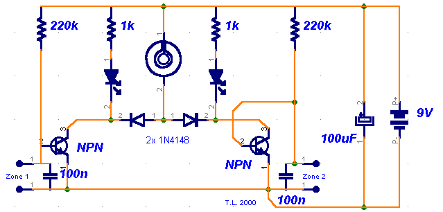
This is the Simple Miniature Loop Alarm Circuit Diagram. The simple construction, reliable operation, very small power consumption, and, most of all, small size. I started with CMOS logic gates, but was soon forced to abandon the concept after a few unsuccessful (and far too complicated) attempts. Then I suddenly realized that a simple transistor switch might do the job and I was right.


Simple Miniature Loop Alarm Circuit Diagram


Simple Miniature Loop Alarm Circuit Diagram


Notes

As you can clearly see from the schematics, the circuit is utterly primitive and consists of two identical transistor switches. Each has its own alarm LED and they're coupled to a neat 82dB buzzer. The two 1N4148 diodes are used to prevent a signal from one sensor from triggering both LEDs. The sensors used are either wire loops or normally closed reed switches or even a combination of both. You could, for example, tie a wire loop to your suitcase and place a reed switch to the door of your hotel room.Since this little alarm is intended to be kept in arms reach at all times, there aren't any provisions for automatic shutdown after a certain period of time. 

The buzzer will sound until you turn the whole circuit off or connect the wire loop back to the jumpers. The same goes for the two LEDs, each indicating its own zone.Construction is not critical and there aren't any traps for the novice. The two 100n capacitors aren't really necessary, I just included them to make sure that there is no noise interference coming from the long wire loops. For transistors, you can use any NPN general-purpose audio amplifiers/switches (BC 107/108/109, BC 237/238, 2N2222, 2N3904...). Assemble the circuit on perf board. Together with the buzzer and a 9V battery, it should easily fit in a pocket-sized plastic box smaller than a pack of cigarettes. A fresh battery should suffice for weeks of continuous operation. 


Author: Tomaz Lazar - Ljubljana, Slovenia


Tuesday, November 18, 2014

0

Simple Cathode led Display Circuit Diagram

This is the Simple Cathode led Display Circuit Diagram. Teledyne TSC7135 DVM chip is used to drive a multiplexed 5-digit display. A CD4513BE CMOS IC, for common cathode drive, is used as a segment driver selected by pins 17-20 of the DVM chip. The transistors can be any suitable npn type such as 2N3904, etc. 

Simple Cathode led Display Circuit Diagram

Simple Cathode led Display Circuit Diagram


Monday, November 17, 2014

0

Using IC 555 Burglar Alarm Circuit Diagram

Burglar alarm circuit or Theft alarm circuits are available in several forms. The above circuit was one of that kind using timer IC 555 as the main component. The circuit is very easy to construct and the cost of this circuit is also very less. So we can implement this circuit by our own and install this circuit in our home so that you can improve your knowledge and it also adds protection to your home.

Using IC 555 Burglar Alarm Circuit Diagram

Using IC 555 Burglar Alarm Circuit Diagram


The working of this circuit is very easy to understand.In the above circuit IC 555 was used as a Astable multivibrator.The Astable multivibrator puts out a continuous stream of rectangular pulses having a specified frequency. Thus by using the Astable multivibrator we can produce continuous frequency which was given as input to the speaker which makes an alarm sound in case of any disturbance in its trip wire. Pin diagram of IC 555 was given below for your better understanding.


Now we can see how we can change the Astable Multivibrator to a alarm circuit.In the above circuit the 4th pin (RESET pin) was connected to the ground using the thin strand of copper wire which is used as a trip in this circuit.The function of the 4th pin that it resets the timing interval when it was connected to the ground.

When the wire was connected the Multivibrator cant produce the rectangular pulses of constant frequency.When the copper strand is cut off then the 4th pin will have no connection with the ground.Therefore IC 555 produces the output pulse and which was given as input to the speaker thus it drives the speaker to give a noise which would scare the burglar away.Thus your homemade effective burglar circuit is readySourced by: Circuitsproject


0

Cheap and Simple Gate Alarm Circuit Diagram

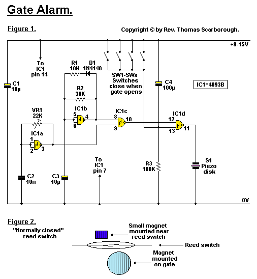
This is the Cheap and Simple Gate Alarm Circuit Diagram. A cheap and simple gate alarm made from a single CMOS Integrated Circuit. 

 Cheap and Simple Gate Alarm Circuit Diagram

Cheap and Simple Gate Alarm Circuit Diagram


Circuit Notes
Figure 1 represents a cheap and simple Gate Alarm, that is intended to run off a small universal AC-DC power supply.

IC1a is a fast oscillator, and IC1b a slow oscillator, which are combined through IC1c to emit a high pip-pip-pip warning sound when a gate (or window, etc.) is opened. The circuit is intended not so much to sound like a siren or warning device, but rather to give the impression: "You have been noticed." R1 and D1 may be omitted, and the value of R2 perhaps reduced, to make the Gate Alarm sound more like a warning device. VR1 adjusts the frequency of the sound emitted.

IC1d is a timer which causes the Gate Alarm to emit some 20 to 30 further pips after the gate has been closed again, before it falls silent, as if to say: "I'm more clever than a simple on-off device." Piezo disk S1 may be replaced with a LED if desired, the LED being wired in series with a 1K resistor.

Figure 2 shows how an ordinary reed switch may be converted to close (a "normally closed" switch) when the gate is opened. A continuity tester makes the work easy. Note that many reed switches are delicate, and therefore wires which are soldered to the reed switch should not be flexed at all near the switch. Other types of switches, such as microswitches, may also be used.


Author:  Rev Thomas Scarborough


Sunday, November 16, 2014

0

Fast Symmetrical Zener Clipper Circuit Diagram

This is the simple Fast Symmetrical Zener Clipper Circuit Diagram. The problem with using two zeners back to back in series to get symmetrical clamping is that the knee of the zener characteristics is rather sloppy. Also, charge storage in the zeners causes speed problems and the zeners will have slightly different knee voltages, so the symmetry will not be all that good. 

 Fast Symmetrical Zener Clipper Circuit Diagram


Fast Symmetrical Zener Clipper Circuit Diagram


This circuit overcomes these problems. By putting the zener inside a diode bridge, the same zener voltage is always experienced. The voltage errors caused by the diodes are much smaller than those caused by the zener. Also, the charge storage of the bridge is much less. By biasing the zener ON all the time, the knee appears to be much sharper.


Friday, November 14, 2014

0

New Simple Lie detector Circuit Diagram

This is the New Simple Lie detector Circuit Diagram. The two probes shown are held in the hands and the skin resistance applies bias to the transistor. 

 New Simple Lie detector Circuit Diagram


New Simple Lie detector Circuit Diagram


The 5 k ohm pot is set for zero deflection on the meter. When the ' 'subject'' is embarrassed or lies, sweating on the hands takes place, increasing the bias to the transistor and upsetting the bridge balance.


Wednesday, November 12, 2014

0

Simple Transmission Indicator Circuit Diagram

This is the Simple Transmission Indicator Circuit Diagram. This circuit the push-to-talk button is closed the light will go on. The antenna samples the output RF from the transmitter. That signal is then rectified (detected) by germanium diode Dl, and used to charge capacitor C2.

 Simple Transmission Indicator Circuit Diagram

Simple Transmission Indicator Circuit Diagram


The dc output is used to trigger a small silicon-controlled rectifier (SCR1), which permits the current to flow through the small pilot lamp. For lower-power applications, such as CB radio, the antenna will have to be close-coupled to the antenna.


Friday, November 7, 2014

0

Simple Preamplifier and High to Low impedance Converter Circuit Diagram

This is the Simple Preamplifier and High to Low impedance Converter Circuit Diagram. This circuit matches the very high impedance of ceramic cartridges, unity gain, and low impedance output. 

Simple Preamplifier and High to Low impedance Converter Circuit Diagram

Simple Preamplifier and High to Low impedance Converter Circuit Diagram


By `loading` the cartridge with a 2M2 input resistance, the cartridge characteristics are such as to quite closely compensate for the RIAA recording curve. The output from this preamp may be fed to a level pot for mixing.


Sourced By: Circuitsproject


0

Electrical Sun powered Alarm Circuit Diagram

This is the simple Electrical Sun powered Alarm Circuit Diagram. This Circuit turns on when light (sunlight) strikes photocell. Potentiometer R sets light level at which the alarm sounds Painted tube (black on inside) may be used on photocell to aim at the sun.

Electrical Sun powered Alarm Circuit Diagram


Electrical Sun powered Alarm Circuit Diagram


Sourced By: circuitsproject


Thursday, November 6, 2014

0

F-V Converter With Sample And Hold Circuit Diagram

This is the simple Frequency/Voltage Converter With Sample And Hold Circuit Diagram. U1 is a frequency/voltage converter, feeding sample-and-hold circuit using an LF381. An LF351 provides 10-V M-scale output. The circuit produces 1-V/kHz output.


F-V Converter With Sample And Hold Circuit Diagram


F-V Converter With Sample And Hold Circuit Diagram


0

High Voltage Power Supply 10kV Circuit Diagram

This is smart High Voltage Power Supply 10kV Circuit Diagram. Be very carefull with this power supply because uses 220V mains and has 10KV at output. Characteristics: supply: 220V AC 50Hz mains Power: 15 Watts Ignition Voltage: 8KV .

High Voltage Power Supply 10kV Circuit Diagram

High Voltage Power Supply 10kV Circuit Diagram


Sourced By: Circuitsstream


0

Simple Watch Tick Timer Circuit Diagram

This is the Simple Watch Tick Timer Circuit Diagram. This circuit adapts a frequency counter to measure intervals. It was originally used as a shutter speed checker for a photo application. The watch ticks are clipped and shaped and formed into a square wave.
 
 Simple Watch Tick Timer Circuit Diagram
 
 
Simple Watch Tick Timer Circuit Diagram
 
 
This square wave is used to gate an accurately known clock (1-MHz TTL XTAL OSC) and an external counter is used to directly count the clock pulses during the interval to be measured. A 1-MHz clock can be used to measure to a resolution of 1 Accuracy = time base 1 1 count LSB.


Sourced By: Circuitsdiagram


Tuesday, November 4, 2014

0

Tester for 74xx04 and 74xx14 ICs Circuit Diagram

The integrated circuits (ICs) 74xx04 and 74xx14 are very frequently used and reused during circuit design. Here xx stands for HC, HCT, AC and LS, etc. Sometimes, the internal inverters of these ICs get damaged. So, it is very important to test these ICs before initiating any experiment and sometimes during the experiments.


Presented here is a simple circuit which can test these ICs statically and dynamically.

Circuit and working
Fig. 1 shows the circuit diagram of a simple tester for 74xx04 and 74xx14 ICs. The circuit is built around hex inverter IC 74HC04 (IC1) and a few other components. You can also test a 74HC14 hex Schmitt trigger with this circuit.

Static testing. The jumpers J1 through J12 are used during static testing of the inverter IC. When J1 through J6 are closed, J7 through J12 should be kept open, and vice versa. When jumpers J1 through J6 are closed, the input of the corresponding inverter is high and the respective output is low. Then, LED1 through LED6 will glow. If jumpers J7 through J12 are closed, the input of the corresponding inverter is low and the respective output is high. Then, LED7 through LED12 will glow. If any one of the LEDs does not glow, it means that the corresponding gate is damaged.


Tester for 74xx04 and 74xx14 ICs Circuit Diagram

Fig. 1: Circuit diagram of the simple tester for 74xx04 and 74xx14 ICs

Dynamic testing. During dynamic testing, jumpers J1 through J12 should be kept open. When jumpers J13 through J18 are closed, oscillations are generated on the output of each gate. The frequency varies from 0.5Hz to 10Hz. Here, both the LEDs will blink alternately. Their blinking frequency can be changed with VR1 to VR6, if needed.


If a gate’s (say, N2) output LEDs do not glow, it means that the gate’s (N2’s) segment is damaged.

IC 74xx04 may not oscillate during dynamic testing because it does not have specified internal Schmitt triggers. So, only IC 74xx14 can be checked dynamically. If all LEDs blink alternately, it means your 74xx14 is fine.

The circuit works on a 5V power supply but you can use a higher voltage supply, within limits specified in the datasheet.

Construction and testing
An actual-size, single-side PCB for the simple tester using a socket for the 74xx04 and 74xx14 ICs is shown in Fig. 2 and its component layout in Fig. 3. After assembling the circuit on PCB, enclose it in a suitable plastic case.

Fix two 6-pin connectors CON2 and CON3 for six outputs. Also fix 2-pin terminal connector CON1 for power supply. Jumpers J1 through J18 are used for external shorting. You have to use eighteen 2-pin berg strip male connectors on the PCB for shorting the jumpers. Fix presets VR1 through VR6 on the PCB for frequency control.


Fig. 2: An actual-size, single-side PCB for the simple tester for 74xx04 and 74xx14 ICs

  
 Fig. 3: Component layout for the PCB

If you want to test an IC, insert it in the 14-pin IC socket. Connectors CON2 and CON3 are provided on the PCB for testing the voltages at each individual gate. Before inserting IC in its socket, verify the test point voltages given in the table (only for inverter gate N1 given here). Similarly, you can verify other internal gates at the respective test points shown in the circuit diagram as well as in the PCB.


 Sourced By: EFY Author: Petre Tzv Petrov


Sunday, November 2, 2014

0

Simple Resistance ratio Detector Circuit Diagram

This is the Simple Resistance ratio Detector Circuit Diagram.  Photoelectric control, temperature detection and moisture sensing require a circuit that can accurately detect a given resistance ratio. A simple technique that uses an op amp as a sensing element can provide 0,5% accuracy with low parts cost. The reed-relay contacts close when the resistance of the sensor Rp equals 47% of the standard Rs. 

 Simple Resistance ratio Detector Circuit Diagram

Simple Resistance ratio Detector Circuit Diagram


Adjusting either Rl or R2 provides a variable threshold; the threshold is controlled by varying R3. For the most part, the type of resistors used for Rl and R2 determines the accuracy and stability of the circuit. With metal-film resistors, less than 0.5% change in ratio sensing occurs over the commercial temperature range (0 to 70 C) with ac input variations from 105 to 135 V.


Social Time

Google Plus
Follow Us
Pinterest
Follow Us

Subscribe to our newsletter

(Get fresh updates in your inbox. Unsubscribe at anytime)